
How to Build a Nostalgic Can-Am Car
The SoCal establishment has been running extremely competitive and fast races for a new class devised by Paul Sterrett and veteran driver Mike Steube, named the Nostalgia Can-Am. The intention of this class is to provide a class of primarily scratch-built slot cars reflecting the spirit of the late-1960s racing era, with scale realism and low cost, to attract newcomers and experienced racers and builders. The idea is to bring the spirit of the late 1960's races with semi-scale bodies such as the ARCO series or even the Rod & Custom series. The rules for this class cas be found HERE.
So far the enthusiasm and the actual racing have been great.
This page shows, step by step, how I built my two Can-Am cars, which are now my favorite road cars that I own. I must mention that these chassis designs were inspired by watching the cars run at the local races and by pictures of Mike Steube's chassis posted on the web. Ever since I saw one at BP raceway, I wanted one. I tried to get on the list for a Steube chassis (since I can be somwhat lazy) but to no avail as they are in too high of a demand, and made in very limited numbers. So, I had no other choice than to build one myself. So I want to give a very special thanks to Mike for promoting and inspiring me to build this type of car.

This page was last updated: August 21, 2006
CHASSIS CONSTRUCTION:
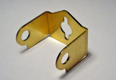
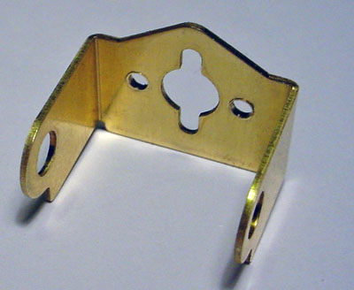
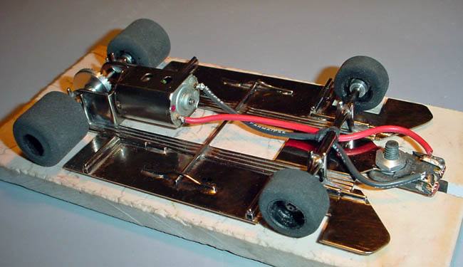
I modified the motor box by reaming the bearing holes to 7/32" to install a piece of tubing to provide a wider and stronger support of the rear axle. I also drilled two horizontal mounting holes for the Slick 7 motor.
It's best (and easiest) to start with a motor box and guide tongue. I got mine from BP Raceway in Buena Park California.
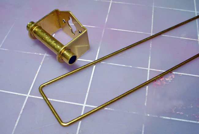
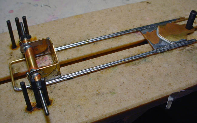
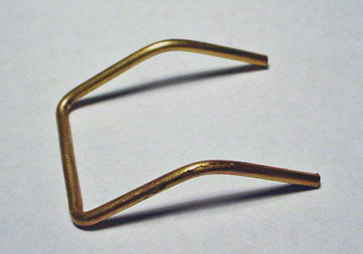
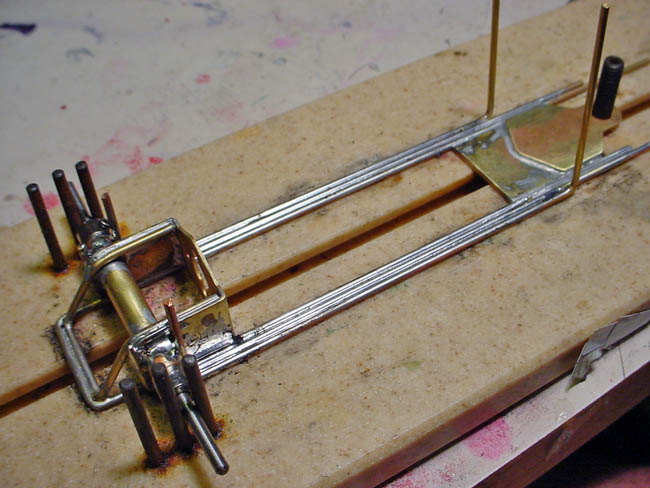
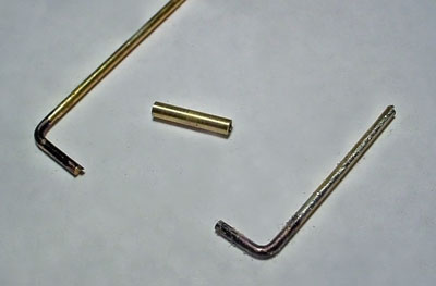
Here you can see the 1.300" piece of 7/32" tubing centered in the motor box. Also shown is a U-shaped piece of 1/16" brass rod. Make sure that the long arms on it at least 5" long. The "U" must be bent so that it is exactly the same width as the gearbox.
With the rear axle tubing soldered in place, place two 3/32" bearings or bushings into the tubing, an axle, and two 3/32 collars to hold everything in place. Then I placed it on a chassis jig and aligned the U-rod to the guide tongue. My guide tongue's guide hole is just over 4 1/2" form the center of the rear axle.

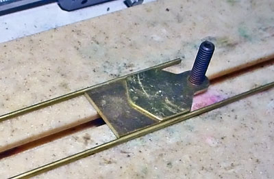
To raise the guide tongue, a small rectangle of .062" brass plate was cut tobe the exact width of the guide tongue and motor mount. In my case, it is .806" wide X 1.00" long. Place it on the jig and with a very hot soldering iron, solder it in place. ( I used Koford 5% silver solder with acid soldering flux)
Everything soldered in place:
(note: at the rear, just make sure that the "U" will clear a gear with a diameter of .830")
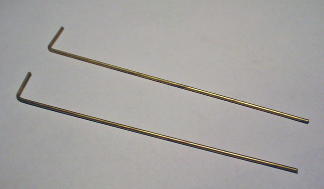
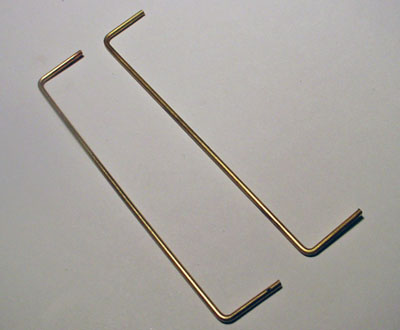
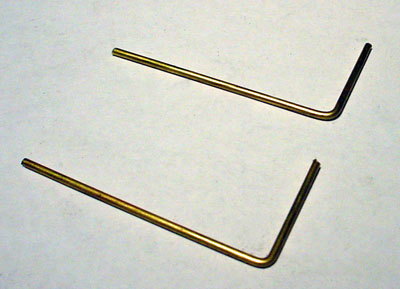
Next, make two "L" shaped rods with 90 degree bends.
Solder them to the "U" frame-One on each side, with the 90 degree bend behind the rear axle tube.
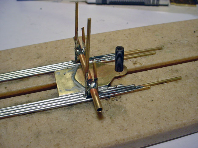
Gearbox stiffener:
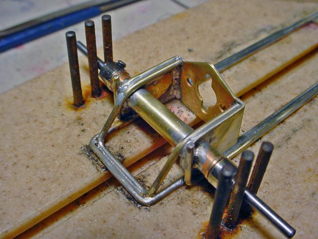
Next, take a short piece of 1/16" brass rod, bend it into a U so that it will fit inside of the main frame's U. Then bend it so it will fit over the 7/32" tubing. It must fit without any pressure, and should just lay right into place. Then solder it into the gearbox as shown in the larger photo below.
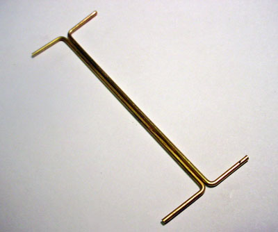
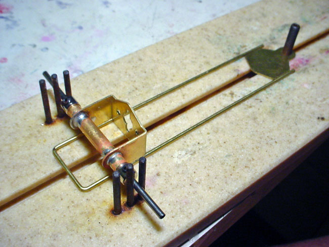
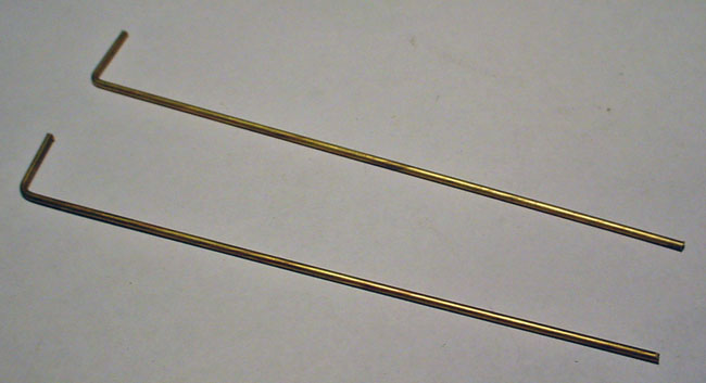
Next, make two long "U" shaped pieces of 1/16" rod. Make them a eaxtly the same as possible. Mine are 3.460" long, measured from the inside of the "U"
Now solder them on, one on each side, to the chassis with the "L" in front of the rear axle tube.
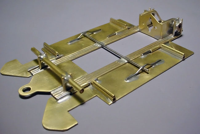
Again, make two "L" shaped rods with 90 degree bends, just like the ones you made earlier for the inner chassis rails.
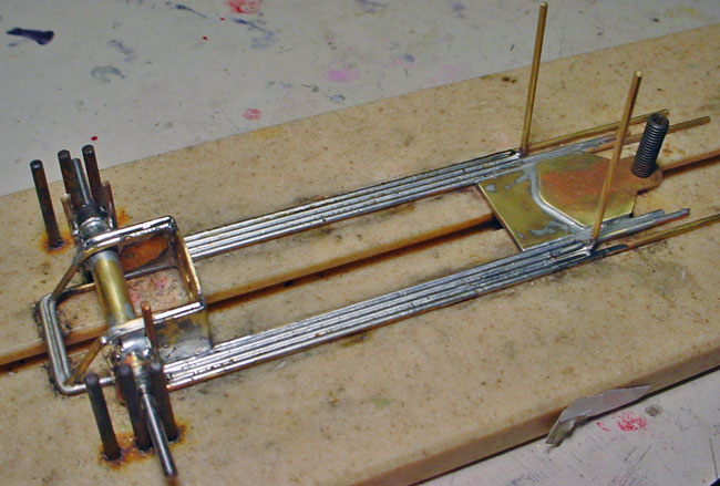
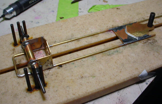
Now solder them in place with the "L" behind the rear axle tubing. Your chassis should now look like this:
I placed the chassis on a chassis alignment jig. I toofk a 2 1/4" piece of 1/8" brass tubing and aligned it for the front axle tube. My wheelbase being 3.750" If you look closely you can see a piece of .032" brass plate underneath the front of the chassis to give the car a clearance of .032 with the .750" wheels mounted. I actually used jig wheels, but if your careful you can use the actual front wheels. In the rear, you can see my .13/16"" jig wheels which gives the car .050" clearance under the rear axle.
When satisfied witht the alignment, solder the front axle tube to the two veritcal supports. If your axle supports are not exactly the same length, just bent them slightly to just touch the front axle tube, without putting any force on it, as you don't want the chassis to be "sprung" in any way.
Another shot of it in the jig. I love this jig as it allows me to get the front and rear axles aligned to easily within a 1/2 a thousandth of an inch! If you build alot of chassis, jigs make your life alot easier and are an invaluable tool, that quickly pay for themselves after just a few chassis builds.
Front axle supports:
Next, make two short "L" shaped pieces of 1/16" brass rod. they don't have to be the same length at all, just make sure the bends are 90 degress.
Now with the chassis back on the first jig, just solder them into the slots in front ot the front axle. Be careful not to overheat them and move the axle tube which you so carefully aligned. It won't take much with a hot tip and good flux. Just do one side at a time an allow it to cool before doing the other.
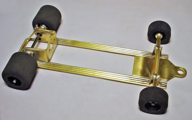
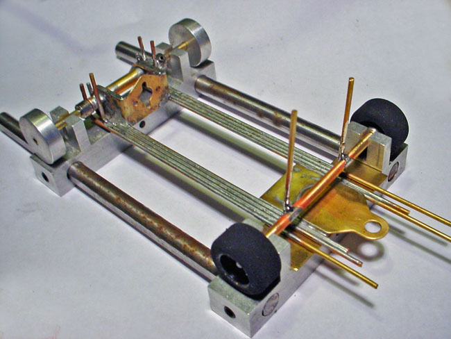
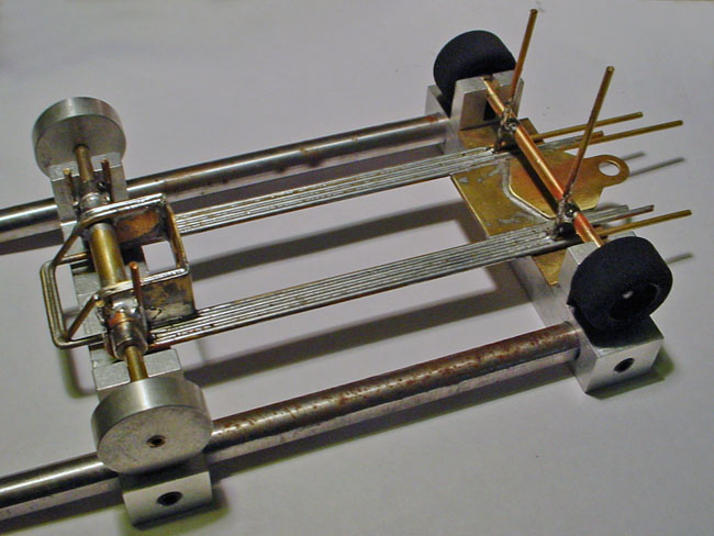
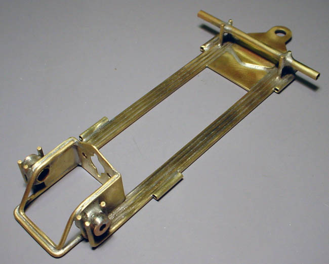
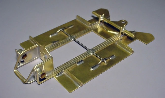
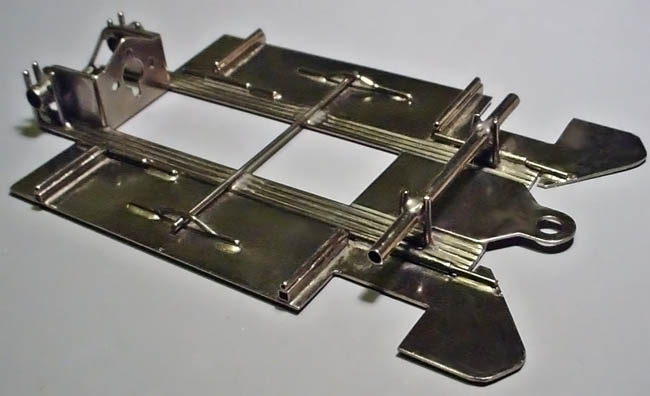
After cleaning it up a little with a scotchbrite pad. The rods are cut even with the front plate, the verticals trimmed evenly, and the rear axle tube's center cut out to allow room for the rear crown gear. If you place your wheels on it, you can now check for the front and rear clearances. It sort of looks like a rigid frame inline indy car chassis at this point.
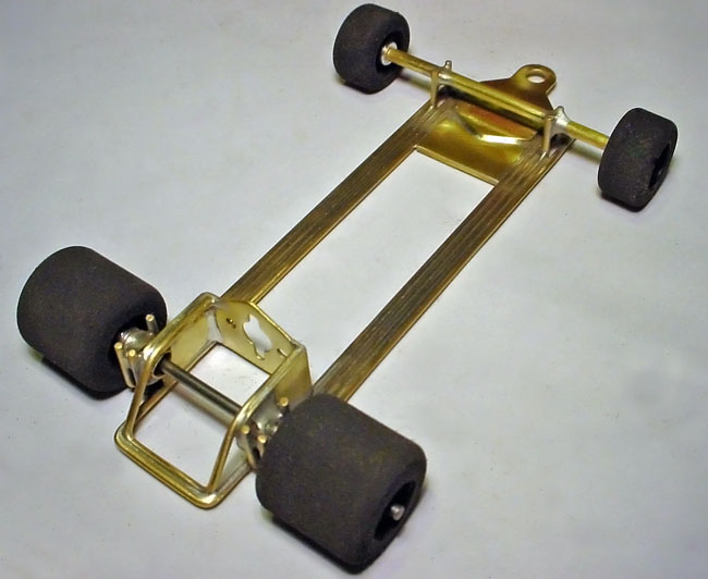
(Click either photo below to enlarge)
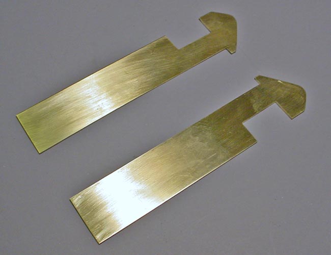
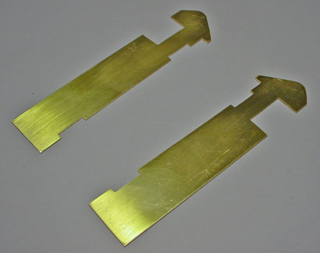
Next, make two body pans out of .032" brass plate. I made these with a dremel with a cutoff wheel and a file.
Body pan hinges:
Make four 1/2 inch long pieces of 3/32" brass tubing. An make two small "L" shaped rods out of some scrap 1/16" brass rod. The trick here is to use a sharpie pen and blacken the ends that go into the hinge so that solder will not stick to them
Place them on top of a scrap piece of .032" plate. This will allow the hinge tubes to be in alignment with the horizontal plane of the pans.
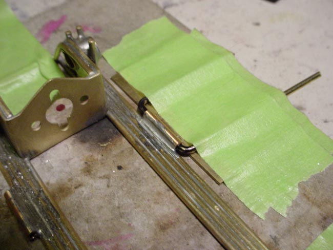
I just taped them securely to the plate and brought it up to the chasiss, then firmly taped down the chassis with the hinge tube in align with the side rail and soldered it in place.
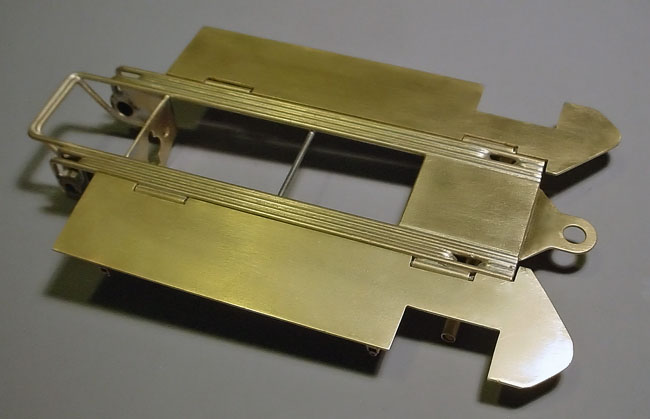
Here's a picture with all four of the hinge tubes soldered in place
Next, I layed the two previously prepared body pans next to the chassis, marked them to make cutouts for the hinge tubes. Make them so that there is approx .030" of play lenghtwise to the chassis.

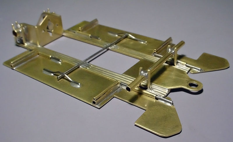
I prepared, inserted and soldered four 1.300" pieces of .055" music wire to the body pans.
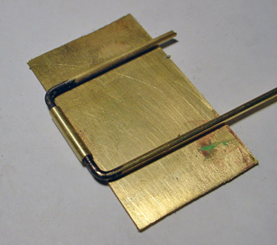
Next, I soldered a piece of .055" music wire perpendicular to the chassis., and then made two .U-shaped 047" stops, soldered to the pan so that the pans cannot fall downward, but can float upward, approx .040". When it's right, the pans can float freely upward and just a little front to back as well. Finally 3/32" square tubing was soldered in place to raise the 1/16" pin tubing body mounts. I actually have made two of these chassis now and made the mounts in the same locations on both of them so that I can swap different body types and styles between them.
(Click any photo below to enlarge)
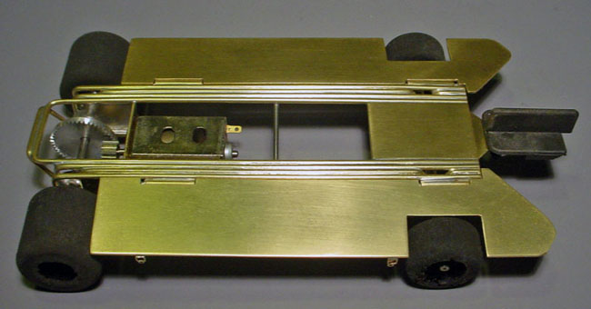
On one of them, I nickel plated it:
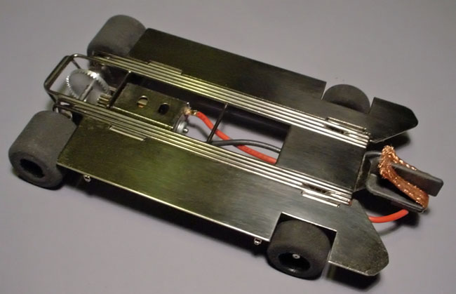
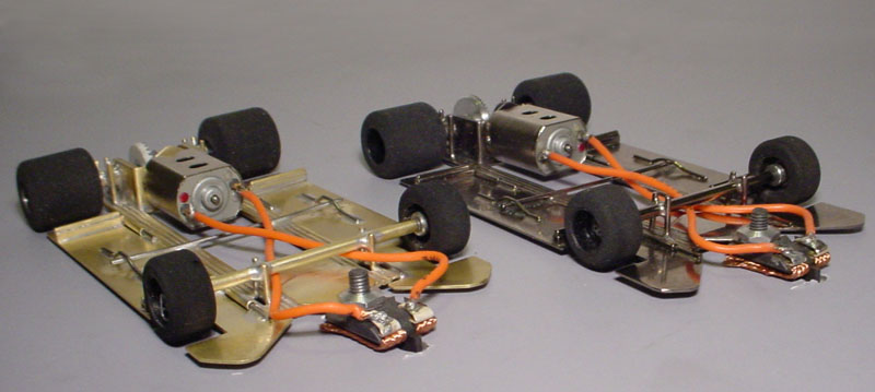
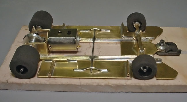
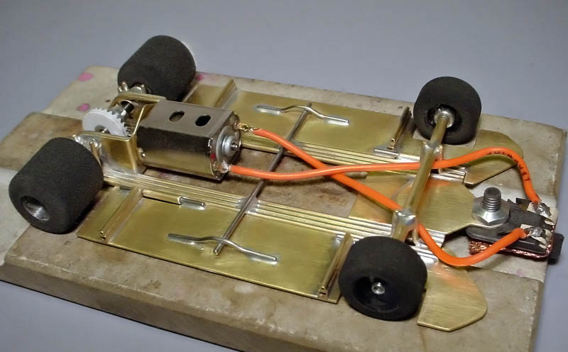
The motors are Slick 7 and I used Sonic aluminum 64 pitch drag gears (14/46) on one of them, and a 28T Spirit crown with a Parma 9T 48P on the other. I used one teflon .005 washer under the guide mount and one 0.15 teflon washer topped with an additional bronze washer with an aluminum nut on top. One of my cars ready to run weighs in at 123.2 grams and the other at 124.1. Both of them run great and handle like a dream. I have tested them on the local track and their lap times are competitive, even with me at the controls! My lap times at the moment are right in the middle of the qualifying lap times. Now it's just up to me to hone my driving skills with more practice.
I hope this page is of help for those who want to scratchbuild a Nostaglic Can'Am car for themselves. For more pics and info on these cars, go HERE . Thanks for looking!
-johnk
When mounting your wheels, use the appropriate axle spacers to bring the front and rear track width to the legal maximum of 3.125".
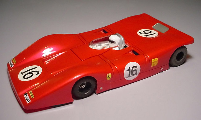
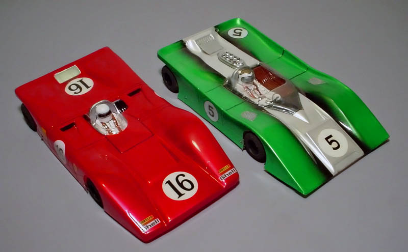
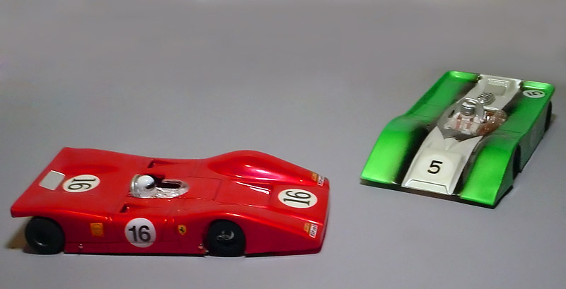
Ferrari 312P
Ferrari 312P Ti22 "Pro"